The Conversion of an Electric Motorcycle
Main Blog | Electric Motorcycle | Electric Jeep | Battery Research
|
So, at one point I told my wife her next vehicle will be an electric SUV with a LandRover Body. Not sure now about the landrover body but I figured before I tried a car which is much more complex, I should convert a motorcycle to electric as they are less complex, cheaper, and would be fun to ride, as I actually ride my bike more then drive my truck. The goal is to experiment and finally make a bike that has a top speed over 150km/h, range over 300km and is fairly inexpensive. I've actually researched and thought on this a lot before I stared this logging. I've decided to try to not purchase commercial electronics but to make my own. I've initially chosen to use a sport touring bike as it: My current bike is a 2007 Kawasaki Ninja 250 which I feel would be a perfect candidate, except, I still want to ride it during conversion, so I'll have to keep looking at the salvage yards for a suitable donor Second, my thought turned to the engine. I got to bang my head for weeks trying to figure out a comparison between a Gas engine and electric and came to the the conclusion that there isn't a conversion factor... Once said I looked at specs for other peoples projects and other bikes. Initially I was looking at 1 50kw engine but realized that no bike sported an engine this big (500lbs). It was easier to get to a size based on weight and came to the conclusion that a 10-15kw motor would be good. Having too small a motor means that you would be stressing it while riding and eventually it will burn out. Too big a motor will just mostly be dead weight. In keeping with experimentation decided to try to convert an alternator to a 3 phase motor (It can be done, I've seen it). Based on the current that alternators come in I decided that 2 alternators rated at 160A should be good. 48v at 2x150 amps gives 14.4kw power which is right in line with what I'm looking for. 2 alternator/motors as they are fairly shallow (so they fit on/in front of engine in a car) we can probably fit 2 horizontally on the bike frame. The shaft would be extended out the back of one and welded to the other so they operate as one. So... We now need a speed controller for a 3 phase electric motor. This is virtually the same as a bldc motor that most RC devices use. I've found smaller Controllers or large controllers for EV's. The EV's are good but are WAY oversized and for a small bike wont work well. Also since we will have 2 motors 2 speed controllers would work well. However, the RC ESC's (electronic speed controller) generally won't handle enough power and if they do are expensive (and goes against building my own). After looking at various controller designs I decided to use the VESC that is Open Source hardware (and software) developed by Benjamin Vedder and can be found at http://vedder.se/2015/01/vesc-open-source-esc/ This speed controller has a number of good features. First, it is open source, so it can be modified if needed, but I dont think there is a need to modify it. The Specs rate it for <60V (I would prefer more but I can live with 48-60v) and 50amps continuous current. The VESC was designed for a motorized longboard (which I find interesting as well). On the longboard the VESC would be in a sealed box with no airflow. The Specs for the VESC has mosfets that can handle 250A continuous and 325A peak current but in an enclosed box the mosfets will overheat quickly. My first thought was to add more mosfets in parallel but besides adding cost and complexity shouldnt be necessary. Researching more, people have been able to pass up to 100A continuously through the VESC if heatsinks are added to the mosfets. I plan on using a heat pipe to transfer the heat to a radiator on the bike so the heat should be dissipated well. Also the VESC's can be chained for serial operation so multiple controllers can be used at the same time for multiple motors. Lastly looking at the charger and BMS. The charger actually is fairly strait forward. I would like to be able to plug to any type of outlet and have the charger convert the voltage to what it needs and to limit the current to what we need (ie, on a 15amp circuit we can blow the breaker if we try to pull 15A off the outlet). Specs I'd like to see is up to 240v and 50A service. Method I thought of is quite simple. First we rectify the AC that comes in to DC... Once in DC we use a Mosfet and flywheel circuit to convert down to ~60v (exact figures to be determined when batteries are figured out). Image kinda explains the circuit
Final cutoff will be done by the BMS. Speaking of which we need a BMS to make sure the lithium batteries (yes, I plan on using Lithium) dont have an accident. The design I originally like is OpenBMS and can be found at http://endless-sphere.com/forums/viewtopic.php?f=14&t=63863 but unfortunalty the chipset on the slave board (ATA6870N-PLPW) is no longer available. I figure I'll change to an LTC6803-2 (Datasheet) But I'll need to rework the circuit for the slave boards. Software is run off an arduino so for the master controller I want to do a circuit board with a socket for a arduino nano. Will create a GitHub account and post that when I get things going. Finally, Batteries..... I'm leaning toward Leaf Battery cells.... but more to come when I figure out more. I'll keep posting when I figure things out.
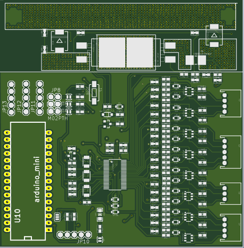
Well, I've been working and thinking on it. BMS: I started designing a BMS sytem for the LTC6803-2... it wasn't until I got so far in to the design that I had to look up the specs and realized I had been designing a circuit for the TI bq7694002DBT (Datasheet).... DOH. I then had to 2 choices, scrap the design and start again, or change my parameters to fit the bq7694002DBT. There are a few differences to think about between the 2 chips. The qb76940 supports up to 16 cell where the LTC6803-2 supports only 12 cells, so I would only need 1 BMS system per 14 cell battery pack which is a positive for the qb76940. Another difference is the LTC6803 has a propriatry chaining bus that you can connect multiple chips together and only manage with 1 master controller, being propriatary though may be harder on the programming side. The bq76940 uses an i2c bus to communitcate which I know how to program quite well, however, the problem comes from there being only one i2c address that is burned into the chip when manufactured. Meaning that I can only use one bq76940 on a i2c bus. So I would need to put another microcontroller (arduino) on each slave board to control the bq76940 (but I can add other i2c devices, like thermometers, etc to be controlled directly on the slave. I decided to stick with the bq76940 due to a number of reasons, cost and flexibility being chief among them. Some design changes will need to be done. First the qb76940 has a regulated output for power but it's 3.3v instead of 5v. This means that my standard arduino nano can't be used. Arduino only has 1 device that comes in a 3.3v variation. That's the Arduino mini. So I'll have to add an arduino and wire the mini directly into the slave board. In the design of the slave board I've still left the i2c pins for connecting other devices. I've also pulled out some of the arduino pins if we want to use them. Lastly, I've pulled out the pins to contect to a SPI bus which will be used for the slave boards to connect to a masterboard. As the slaves are now more intelligent each board can run by itself as a unit and does not need any other components to manage the batteries. The SPI bus connecitng the slave boards to a master is for passing information to the master when called for for user display and user control when needed. Overall I think this will be a better design. Here's the PCB Board Design:
[Slave PCB Design] [Slave Schematic] The design was originally done with a arduino nano (yes it says mini... but someone screwed up the names in the kicad library). When I get a mini I'll design the foot print and redo the board to match. Motor: Worked on the test motor... took the alternator apart, removed the regulator and rectifier. Charged up a S6 battery and hooked up a speed controller. Motor didn't turn, but it should have. I'll have to see what I did wrong. Hopefully will do that tonight. Anyway... Guess that's all for now. So.. worked on in and have a defined BMS Board.... Looks to be complete except for clean up (ie, silk screen and some touchup).
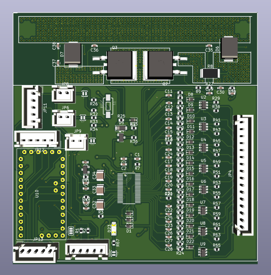
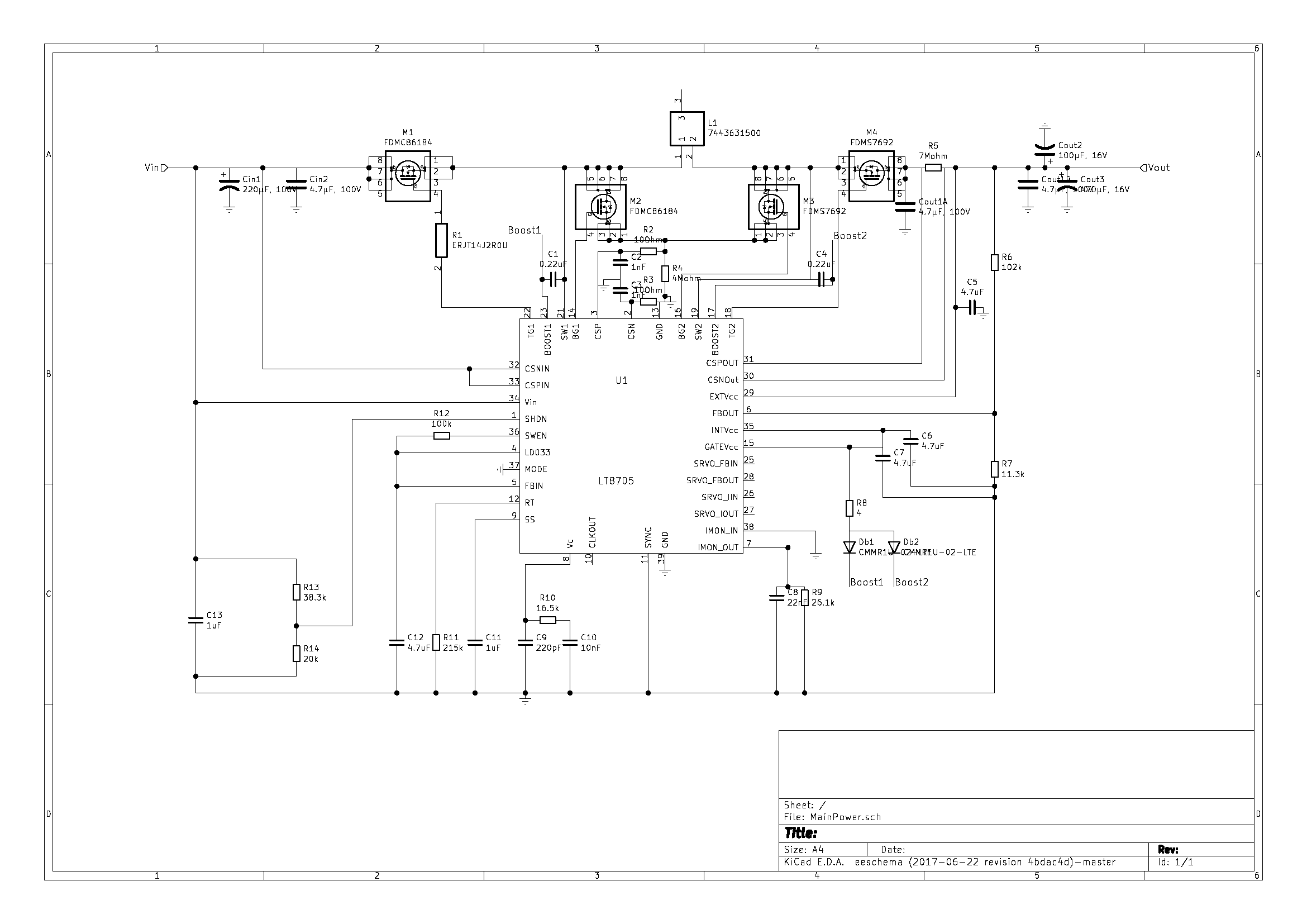
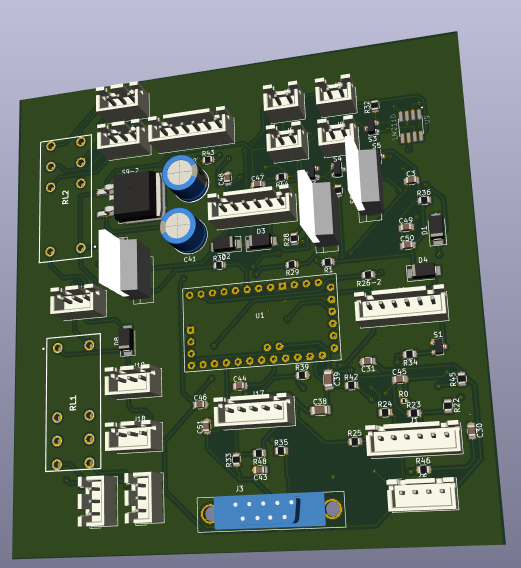
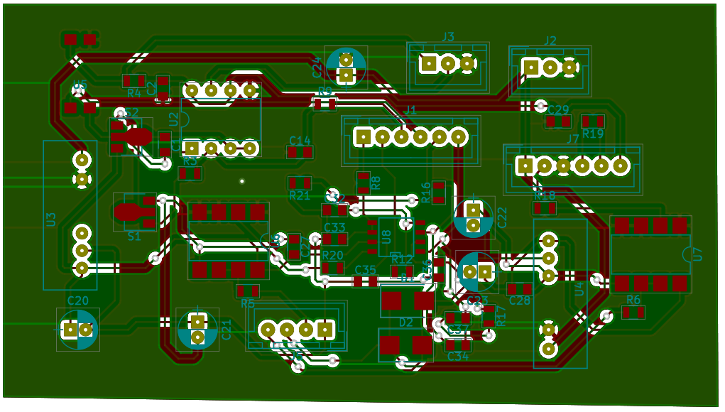
I think I'll stop for now. I'm focusing more now on what is needed for the power to the bike. Basically I need a power supply with a couple of specs: 1) takes 14s (~52v) input 2) pull off 1.5-12v variable power for control of the rotor magnet. This should control torque vs rpm, kinda like an electric gear shift. 3) pull off 12v for all other regular electrical stuff on the bike. Need a high current for this. May need to do 2 IC's 4) pull off 5v for electronic components. This unit will also probably also take in throttle setting and do speed control (at least repeat to the VESC's). Also we should probably monitor the current during operation (but I think the VESC's will output current). I'm just researching IC's to do the buck conversion. Ok.. figured out our main power distribution. This will be using IC's for the converters. Also there is no MCU, so mostly just dumb service The board takes in the 14s input and splits it via 3 converters. 1) MainPower: The main power for the board is via a LT8705 which will allow 5v-80v converted down to 12v and allows 45A of running. FieldController could plug into this but will put another 5A down converter dedicated to the job. Have to change out M3+M4 mosfets for the current (Maybe use the current one we use for M1+M2). Will also need to check components in the power line.
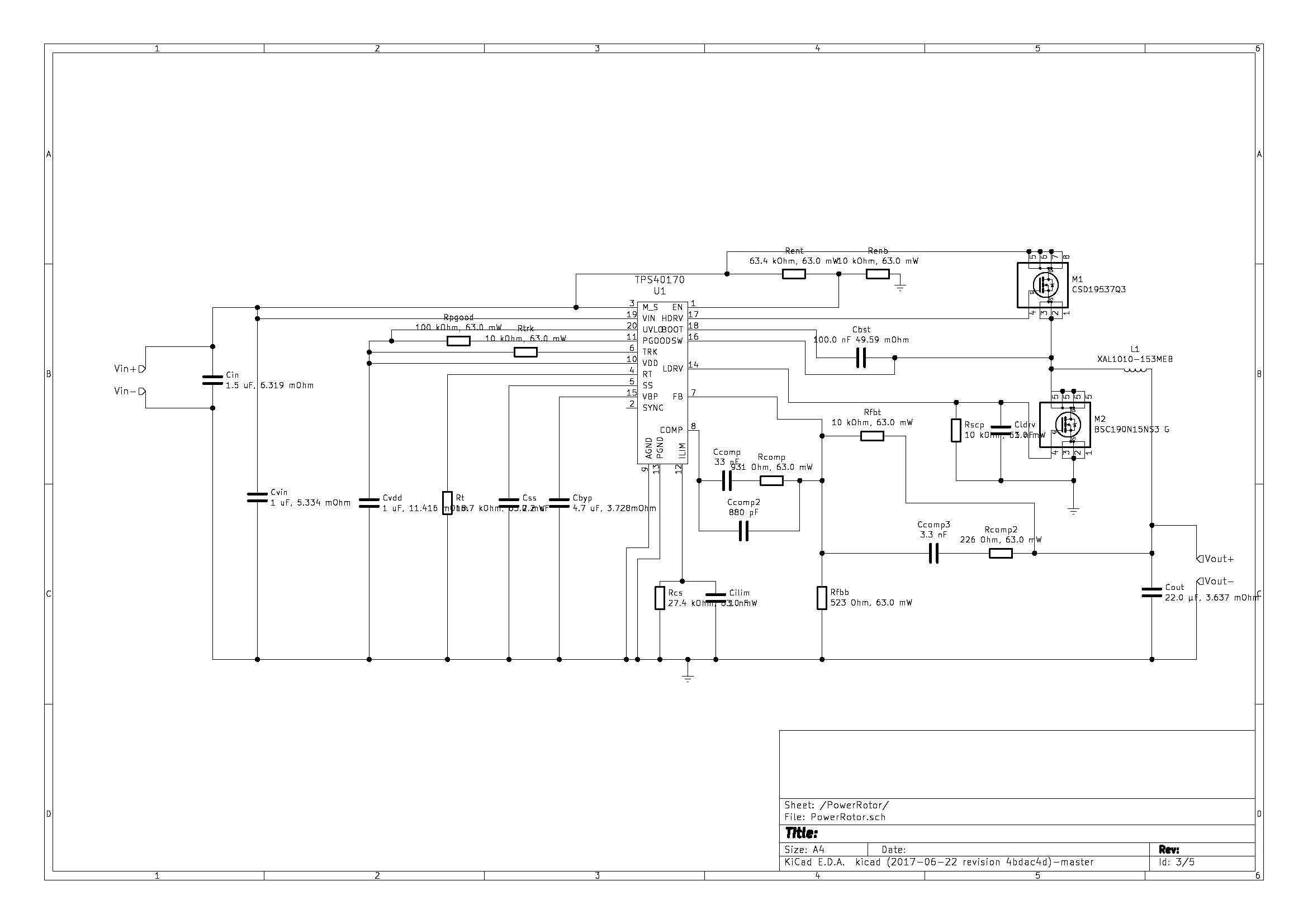
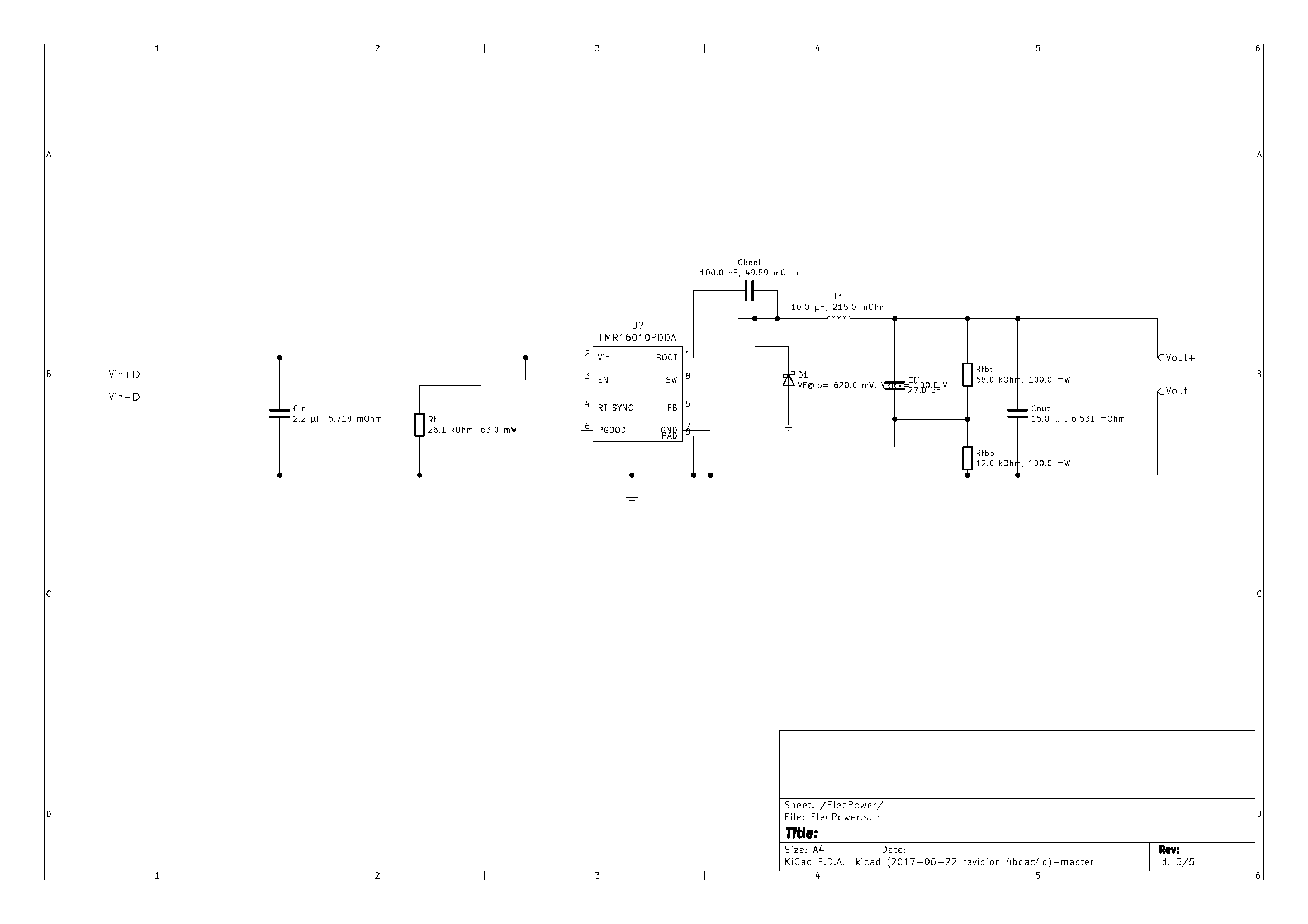
2) RotorPower: This is a 12v 5A circuit using TPS40170RGYR IC. From this we have a simple speed controller. 3) ElecPower: Electronics power is 5V 1A using LMR16010PDDAR IC. This feed all the electronics I also found a fuel guage IC LTC2944... will have to look into it. Thats it for now... will keep updating as I go Ok.. got the Schmatics done for the Electronics power and for the rotor power. Also I've decided to use the LTC2944 and put it in the power management board. Still have a bit to do for this but getting there Rotor Power
Electronics Power:
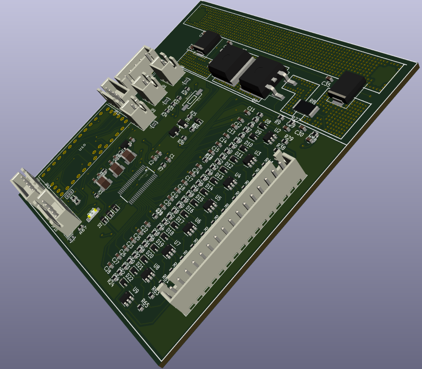
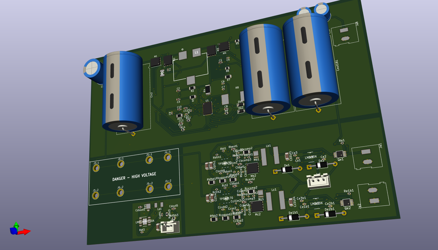
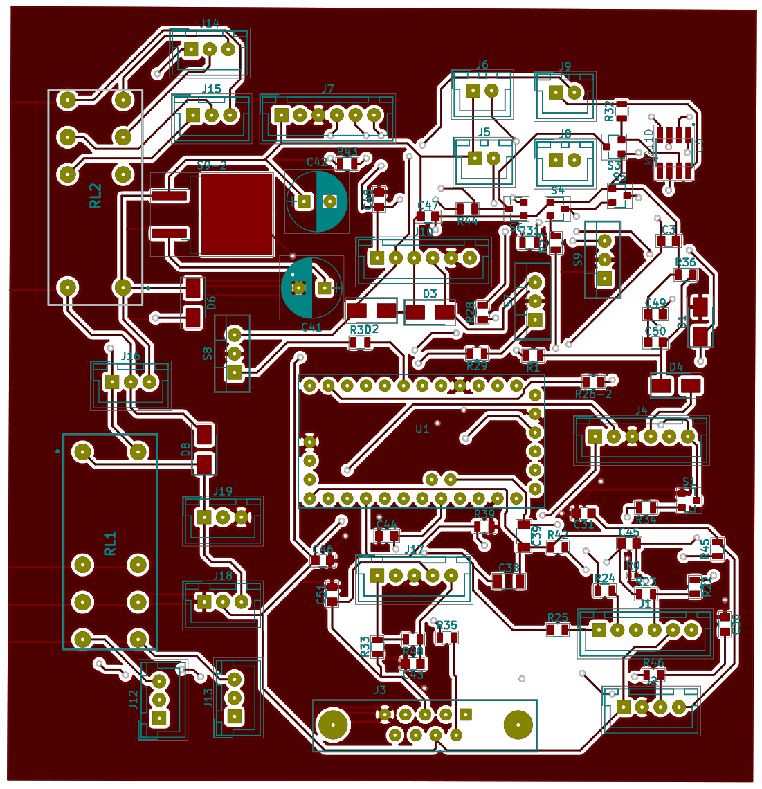
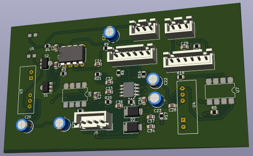
Ok.. enough for tonight... will keep posting when more is done. Ok.. finally got the Power Distribution circut designed.
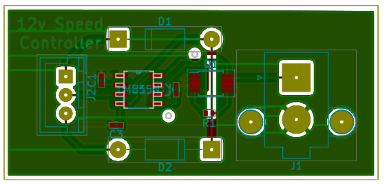
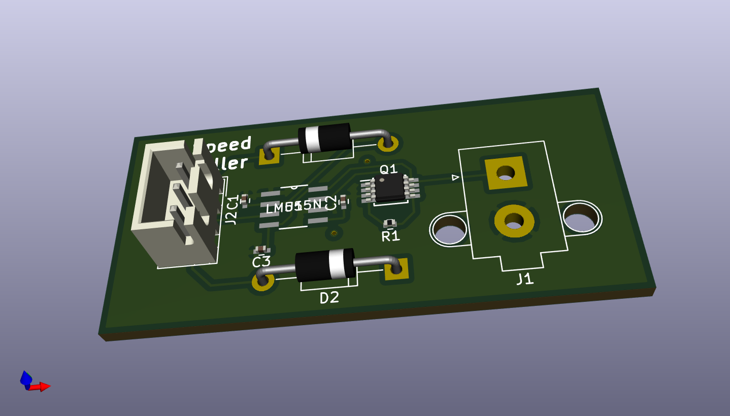
Next is the charger and the Logic Board. Also I've been looking at if a conversion is worth while or if I should just build my own frame as I can make it fit the batteries better. I figured I'd use the fairing (or frame) of a VFR800 as it follows the specs. Ok.. realized I needed a variable voltage system (kinda like a speed controller for an brushed motor) so I can test the various voltages and their effect on the alternator motor when applied to the rotor. I removed that part of the design from the power management and did up a pcb.
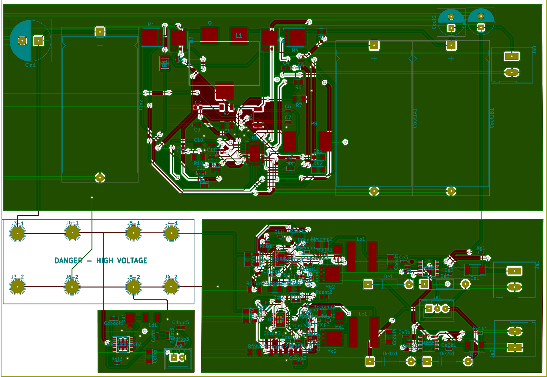
I've included all the files >HERE< and went and ordered the parts and had the PCB printed at oshpark.com (was ~$9.50 for the printing). If anyone feels like using the design feel free to download the files. I may also have a couple of spare boards I can sell. Wow, It's been awhile.. Works been busy. But have made steady progress without anything worth while to say. Anyway, Close to finishing design of charger. Schematics below: Controller
Driver Board:
Power Board (I havent done the layout yet):
I'm still working the design.... and I'm sure I'll have to redo the layout..... but its coming along. I'll try to not go so long without posting
|